+
 Artist's conception of an SR3 panel
 Actual SR3 prototypes
November, 2015 – Solar Roadways Incorporated is awarded a Phase IIB SBIR (Small Business Innovative Research) contract by the U.S. Department of Transportation. The 2-year $750,000 Phase IIB contract includes additional civil engineering tests including:
Freeze/Thaw Cycling: Panels will be placed in an environmental chamber and exposed to extreme temperatures to make sure the mechanical/electrical systems hold up.
Moisture Conditioning: Additional environmental chamber testing. This time, the panels will be frozen into a block of ice and then thawed – many times.
Shear Testing: Panels will be subjected to high shear forces to simulate heavy vehicles braking.
Advanced Loading: Will simulate years of truck abuse in a matter of months.
While we plan to begin with non-critical applications such as driveways, parking lots, sidewalks, bike paths, etc., these civil engineering tests will get us closer to being ready for public roads and highways – our ultimate goal.
SR3 prototypes
As can be seen in the picture above, higher intensity LEDs have replaced those of the SR2 panels. They’re easily seen in the daylight now. The mounting holes have also been removed to allow for more surface coverage with the solar cells. SR2 was a 36-watt panel and the SR3 is a 48-watt panel of the same size. The edge connectors should make installation easier. More to come on that subject after the first SR3 installation.
Thanks to the many people from all over the world who donated to our first and ongoing Indiegogo campaigns, we’ve been able to purchase some equipment for both prototyping and manufacturing. Among some of the larger acquisitions:
 CNC machine for glass
 Kiln
Kiln CO2 laser
 Newly arrived reflow oven
 Scott's favorite
 Glass working table
 Raw glass cart
 Finished glass cart
 Artist's conception of an SR2 panel
 Actual SR2 panels
July, 2011 – Solar Roadways Incorporated is awarded a Phase II SBIR (Small Business Innovative Research) contract by the U.S. Department of Transportation. The 2-year $750,000 Phase II contract is to build a proof-of-concept parking lot made of Solar Road Panels and to conduct civil engineering tests including:
Load Testing
Traction Testing
Impact Resistance Testing
The Phase I prototype (see bottom of page) proved that the basic electronics would work, but never left the inside of the lab. The prototypes of Phase II were actually exposed to the elements and civil engineering tests.
One lesson learned during Phase I was that a 12-foot by 12-foot road panel wasn’t very practical: It would be extremely heavy and difficult to transport. Another is that large squares make poor building blocks around curves and over hills.
The Phase II prototype was reduced to a hexagon shape measuring approximately four square feet. The end result weighed 110-pounds, so an individual would be able to place them in a vehicle to transport them to a site. The small hexagon shape also allowed SR2 to accommodate curves and hills.
LED technology has been around for decades, as have microprocessors. Heated glass has been in the rear windows of cars since at least the 70’s. President Carter had solar panels installed on the roof of the White House in 1977. These proven, time-tested technologies make up the bulk of a Solar Road Panel.
The big hurdle was the glass surface: no one had ever attempted to make a driving surface out of glass. Could it handle the abuse of a fully-loaded semi-truck? Could the surface be textured in a way to prevent vehicles from sliding on a wet surface, while still allowing sunlight through to the solar cells beneath? This is where the bulk of the R&D would be focused during our Phase II research.
Glass samples were sent to a civil engineering university for traction testing. We started the testing with a glass sample of an ADA (Americans with Disabilities Act) approved stair tread. A British Pendulum tester was used to test the traction of the glass.
In layman’s terms, the test result showed a surface that could stop a vehicle traveling 40mph on a wet surface in the required distance. This was all that was really needed for the prototype parking lot requirement, but the final goal has always been highways. The stair tread texture was improved upon and more samples were sent out for traction testing. The numbers kept rising until we finally had a texture that could stop a vehicle traveling 80mph on a wet surface in the required distance.
In the process, several different surface texture patterns were tested. Some patterns tested better than others. After studying the results of the different macro-textures, we then designed our own honeycomb macro-texture for testing. This one tested better than the others and proved to be the optimal design.
Finding a glass manufacturer proved to be a challenge. By glass industry standards, our order would be considered small, it was a very specialized custom order, we needed it fast, and we had a limited budget. Tim Casey of Jockimo Glass came to the rescue and produced the glass for us. We later used his shop in Aliso Viejo, California for the final assembly of the 108 SR2s that went into the prototype parking lot.
Glass samples were also sent off too another civil engineering university for load testing and impact resistance testing. The load testing showed that a pavement made of our SR Panels could withstand a static load of 250,000 pounds. To put that in perspective, the national weight limit for semi-trucks is 80,000 pounds. So the test results indicated that SR Panels can withstand more than three times the legal load of fully-loaded semi-trucks. These results were incredible but needed to be reconfirmed, so we were asked to perform a 3D Finite Element Method analysis (computer simulation) at a different civil engineering university. The results came back the same: 250,000 pounds.
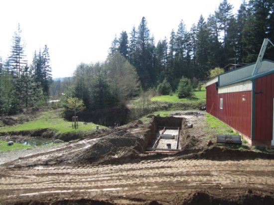
The site for the prototype parking lot was chosen. It would be installed on the south side of the SR electronics shop in Sagle, Idaho. Ten percent of the aggregate used in the base was recycled glass.
 Beginning construction alongside the electronics lab
 Side of the Cable Corridor
 Road bed in place
 Conduit installed
 Deer solution
 Base poured - contains recycled glass
 Cable Corridor and base completed
 Testing the solar cells
  Installilng the solar cells
 Once back in Idaho, shipments of completed panels began to arrive from Jockimo. Scott tested them one last time by lining up six panels in the shop and allowing them to run for 24-hours before installation.
After 24 hours of initial testing, the 6-panel row was installed and placed online. Unfortunately, due to several delays by subcontractors and suppliers, the installation of the prototype parking lot in began in December – in north Idaho.
Scott’s LED Blunder
The initial LED layout included 51 white and 51 yellow LEDs per hexagon panel. These were to simulate any current road line configurations. High intensity LEDs were chosen so they’d be easily seen in the daylight.
The microprocessor circuitry allowed for 128 input/output lines for the LEDs, so that left 26 unused I/O lines. Julie asked Scott if he could add additional colors for variety, so he added 9 red, 9 green, and 8 blue LEDs. Blue LEDs were still relatively new at the time and Scott couldn’t find any that could match the intensity of the white and yellow LEDs that he’d already selected. Not wanting the blue LEDs to be “washed out” by the other LEDs, Scott changed the specs so that the other LEDs were closer in intensity to the blue LEDs. He’d made his wife happy and never thought of it again, until one day…
All testing of the LED systems had taken place indoors – both in Idaho and California. Once the panels had been tested, assembled, hermetically sealed for outdoor use, and then tested again, they were ready for installation. It wasn’t until the first row was installed and activated in the sunlight that the problem was noticed: even on their brightest setting, the LEDs were difficult to see (and more difficult to photograph) in the daylight. We knew it would be a very easy fix for the next prototype, but it was frustrating not to be able to show the parking lot lights in the daytime.
The installation continues
As each row was installed, cabling was fed through the conduit and into the Cable Corridor, where it would be connected to another circuit board in a weatherproof utility box. Since it was winter, many of the conduits were filled with ice. A hairdryer was used to melt the ice prior to pulling the cables through.


The Cable Corridor was designed to allow a grown man to crawl through it. No consideration had been given to said man wearing a winter coat however. One could wear a sweatshirt, but nothing thicker. Needing dexterity to make all of the wire connections, gloves were not an option. This picture was taken when it was 5 degrees (F) outside. Scott could work for about 20 minutes in the cold before needing to warm back up in his office.


 The completed prototype parking lot

As stated earlier in the report, all of the measured results were done in Sagle, Idaho near the Canadian border at a longitude of 48.2024 degrees north. To put this in perspective, the northernmost point of Maine is at longitude 47.46 degrees north, which is several miles south of the Sagle, Idaho testing area. The farther south one travels, the better solar harvesting one can expect. Therefore, the rest of the U.S. could expect to generate more power than the test results show in northern Idaho.
In the original solicitation, eight attributes for a new type of pavement were defined:
1. It generates its own power; either through the energy of the sun or perhaps the energy of the moving vehicle mass traveling over the pavement.
In the Solar Cells section, it was learned that a micro-inverter recorded 52397Wh from the output of four hexagon Solar Road Panels over a six-month period.
Each full size hexagon panel measures four square feet, so there would be 15,840 panels per lane mile using a 12-foot wide lane. If each four of these produced 52397Wh in six months, then the same four would theoretically produce 104,794Wh per year. That's 26.1985kWh per year each. Multiply that by 15,840 panels, and the road would produce 414.984MWh per year per lane mile. This is with only 69-percent solar cell coverage. With 100-percent coverage, the output would be 601.426MWh per year per lane mile.
In the LEDs section, it was learned that it will take 704-watts per lane mile to illuminate a standard road line configuration. Multiplying this by 24 and by 365, it is seen that the road will require 6.167MWh per year per lane mile for the LEDs. This assumes leaving the LEDs on 100-percent of the time, which is unnecessary.
In the Microprocessor section, it was learned that the microprocessor and supporting circuitry would use 12.136kW per lane mile while active, and 536mW per lane mile while in sleep mode. Assuming worst case - that the microprocessor is active 100-percent of the time: 12.136kW times 24-hours times 365-days equals 106.311MWh per year per lane mile. If used in sleep mode, it would only be 4.695kWh per year per lane mile.
Power generated (414.984MWh) minus power needed by the microprocessor and supporting circuitry (worse case - 106.311MWh) minus power required by the LEDs in a typical road line configuration (left on 100-percent of the time - 6.167MWh) leaves 302.506MWh per year per lane mile to be distributed to surrounding homes and businesses or to be used to charge electric vehicles. According to the U.S. Energy Information Administration: In 2012, the average annual electricity consumption for a U.S. residential utility customer was 10,837 kWh. Using this number, approximately 30 homes per lane mile could be taken off grid with a Solar Roadway and an efficient energy storage system. It would be 43 homes per lane mile with 100-percent coverage. So a simple 2-lane rural road could take 86 homes completely off-grid along the Canadian border. The farther south the system is used, the more homes can be taken off-grid.
In northern climates, the heating elements can use up to 2.281MW per lane mile with the heating elements constantly on. Since they only need to be on during the winter months and sporadically even then, it is difficult to calculate the total power required to get through a winter. It would vary greatly from one location to the next and from one winter to the next. The costs of running snow plows and the chemicals used by the plows would offset the cost of the electricity needed to run the heating elements in the Solar Roadway system.
2. It is intelligent enough to transfer the power generated to where it is most needed or to a temporary storage apparatus.
The DC energy from the solar cells can be arranged in any series/parallel combination to produce whatever voltage/current requirements are needed. This allows that the system can be connected to any type of storage device available.
In the prototype system, a virtual storage system was used: the micro-inverters converted the DC energy from the solar cells into 240VAC, which was then fed into the load center at the Solar Roadways facility. The power was used by the building during the day. Any excess power was placed on the grid for future use (net metering). When needed (such as nighttime), power was drawn off the grid to power the system.
In this way, the pavement can power surrounding homes and businesses. As advances are made in the field of energy storage, the Solar Roadways system can implement the new technologies where desired.
3. It is made of recycled or other sustainable materials.
Recycled glass was used for ten percent of the aggregate in the base. The internal support structure can be made of recycled plastic. Virtually everything in the system can be reused or recycled with in keeping with the "Cradle to Cradle" design philosophy being used.
4. It can be modular for ease of replacing worn or damaged sections.
Each Solar Road Panel works independently and no two panels are physically connected to one another. They are mounted to the base in a backplane style with one 6-conductor plug and four retaining bolts. The panels communicate with one another and can report in when a panel stops communicating. Each panel currently weighs 110-pounds, so a maintenance worker could bring along a good panel to replace a non-functioning panel. Four nuts are removed, the old panel is unplugged, the new panel is plugged in, the four nuts are reinstalled, the panel is programmed, and the maintenance truck leaves. This should take no more than five minutes. At this point, the road will be like new again, rather than any kind of "patch fix".
5. It is durable enough to withstand repeated loading from heavy traffic at or above the level of current pavement systems.
Load testing is discussed in the 2.3.1 Load Testing section. The testing showed that the Solar Roadways system could withstand the loading of a 250,000-pound truck.
Additional 3D FEM testing confirmed the 250,000-pound truck loading ability of the system.
6. It meets or exceeds safety characteristics of existing pavement systems.
Traction testing is discussed in the 2.1 Surface Traction section. A British Pendulum Tester was used and the samples exceeded the desired Skid Numbers. According to the tester, asphalt with these skid numbers qualifies for vehicles traveling at a mean speed of 80mph on a wet surface.
Solar road studs - LED devices that are installed on road lines to alert drivers where the lines are at night - have been shown to reduce nighttime accidents in the UK by 72-percent (http://www.clearviewtraffic.com/images/file/White%20Papers/Five%20ways%20to%20make%20night-time%20driving%20safer.pdf).
Likewise, road lines illuminated in the Solar Roadways system will provide even more nighttime visibility and safety by illuminating the entire lines and adding verbiage and warning systems.
With an intelligent road (microprocessors positioned roughly every two feet), the traffic management capabilities are endless. Scott Brusaw was the keynote speaker at an annual Intelligent Transportation Systems conference. Many of the vendors approached Mr. Brusaw afterward with the same concerns: their traffic management systems needed both power and communications in remote locations. The Solar Roadway system offers both.
In addition, the prevention of snow/ice accumulation will prevent countless accidents across northern climates, including pedestrian and animal collisions.
7. It mitigates water runoff through either permeability or designed retention and filtration.
As learned in the 5.3 Stormwater section, stormwater can be filtered and retained in the Cable Corridor. It can then be moved either direction along the road to wherever it is desired, such as an aquifer or an agricultural area.
The flexibility of this system allows owners (parking lots, driveways, city streets, etc.) the option of treating stormwater on site and then using it for irrigation, gray water, landscaping, etc.
8. It is at a cost that allows it to be financially self-sustaining; meaning that the benefits of power generation and water runoff mitigation over the design life outweigh its initial cost.
The combination of the power generation, leasing of the accompanying Cable Corridor to power and data companies, water runoff mitigation, and potential advertising (parking lots) should cover the costs of the system. None of this even takes into account the amount of subsidies available for renewable energy projects.
The original solicitation further states that, "Phase 2 efforts include manufacturing and demonstrating a working prototype pavement system that demonstrates potential for achieving at least 1/2 of the identified attributes."
Potential for all eight of the identified attributes have been demonstrated. The technology works and, if the results of the Solar Roadways Indiegogo campaign and the multiple letters of interest are any indication, the world is ready for this technology.
 Artist's conception of an SR1 panel
 Actual SR1 panel
August, 2009 Solar Roadways Incorporated is awarded a Phase I SBIR (Small Business Innovative Research) contract by the U.S. Department of Transportation. The 6-month $100,000 Phase I contract is for “a detailed concept that demonstrates the viability of creating a prototype that satisfies the attributes described below:
Phase 2 efforts include manufacturing and demonstrating a working prototype pavement system that demonstrates potential for achieving at least ½ of the identified attributes.” (listed above – see Phase II Final Report Conclusions in the Phase II Research section)
Glass
To make a solar panel that could withstand the abuse of fully-loaded semi-trucks, a protective case had to be created to protect the sensitive solar cells and electronics inside. In addition, the surface of this case had to be transparent to allow the sunlight to reach the solar cells inside.
Deciding what to make this protective case out of was a materials engineering problem. Scott Brusaw is an electrical engineer (BEE, MSEE), so he looked up the top materials research labs in the nation. Penn State’s Materials Research Institute and the University of Dayton’s Research Institute were at the top of the list. Scott traveled to both universities and met with their materials research professors. Both research labs, without hesitation, suggested the use of glass for the surface. Unlike plastic, the optical properties of glass are stable against solarization (long-term darkening) and other UV induced mechanisms of material degradation. Float glass was recommended due to its widespread commercial availability and relatively low cost.
 Testing the transmittance of float glass
Float glass comes in different forms. The greenish glass shown above is called soda lime glass and is the most common type. Windows and bottles are typically made of soda lime glass. The green tint is caused by the iron content of the glass. This same iron content negatively affects the transmittance (ability to pass sunlight) of the glass, so a low-iron glass was selected.
Due to the very limited budget of the Phase I prototype, glass was only studied, but not yet used during this round of funding. The findings were applied in Phase II.
Stormwater
Stormwater is just rain or melting snow that makes its way from our roads to our waterways. Imagine a heavy downpour: the stormwater flows across lawns/fields and picks up fertilizer, pesticides, etc. It then flows into the street, where it picks up vehicle droppings such as oil, antifreeze, etc. Currently, this toxic cocktail finds its way into our streams, rivers, lakes, and oceans. Some studies show that over 50-percent of some water pollution is caused by stormwater.
Capturing and filtering the stormwater before it reaches the waterways could solve the problem. A physicist/hydrologist once shared that, if we could move water just 200 miles in this country, we could eliminate drought conditions.
By lining the sides of our roadways with stormwater retention systems, we could do the initial filtering. By including pumps, the stormwater could then be moved to areas for additional filtering and then to aquafers or agricultural centers. In colder climates, the stormwater could be stored below the frost line to prevent freezing.
 Cutaway view of stormwater retentions system
 Side view of stormwater retention system
Electronics, firmware, and software
The SR1 was designed around a 32x32 array of LED cells. Each cell contains 3 white and 3 yellow LEDs to simulate any road line paint configuration. This required 64 circuit boards to create the 12-foot by 12-foot SR1. Another circuit board was needed for the microprocessor control unit.
 LED circuit board - 64 boards per panel
 Microprocessor board
Scott Brusaw designed the two circuit boards required. 68 of the LED circuit boards were assembled and tested: 64 for the SR1 and another four for a prototype crosswalk panel. Three microprocessor boards were assembled and tested. These were the control/communications boards for the stormwater control system, the Solar Road Panel, and the Sidewalk Panel. An XBee RF module was added to the microprocessor board to incorporate wireless communication.
Scott then wrote the firmware for the microprocessor boards. A software program was needed for testing and control, including:
Configure which LEDs would turn on/off
Control the stormwater pumps
Read/control the crosswalk panel
Scott concurrently wrote the firmware and software programs for the desired interactions.
 Screenshot of the testing software
Once all of the testing was done, it was time to assemble the panels. Scott and Julie had built an electronics lab on their property in Sagle, Idaho, but the shop floors were still dirt at the time and therefore unsuitable for the panel assembly. A good friend offered his shop space for the task.


The idea was to assemble and test the panels, film a demonstration of the system, and then break everything down again. Helpers were on hand and Mark Dixon of YERT was visiting from Pennsylvania to do the filming.
Here’s where Scott made the worst mistake of his career: the SR1 used two power supplies – a 12-volt supply for the LEDs and a 3.3-volt supply for the control circuitry. In the hurry to get the panels assembled, Scott connected the power supplies incorrectly. 12-volts was applied to the 3.3V control circuitry, destroying all of the IC chips (640 of them) in the system. Replacement parts were ordered and delivered overnight. Scott, Mark, and other helpers spent the next two days desoldering and replacing the damaged ICs.
Once everything was repaired and running properly, filming began and pictures were taken.
You can see YERTs film, The Prototype here:
Scott drove Mark Dixon back to the Spokane Airport once the filming was done. Mark, reflecting on what had taken place, said, “You know what I found amazing? As miserable as it was having to repair all of those circuit boards, no one got upset. Everyone remained cheerful and just did what it took to repair the system and move on. What a great team.”
