SR Technology Behind the Scenes
I’m Scott and this is my first blog. I’m so busy with the technical side of Solar Roadways that I don’t have much time for writing. They keep me hard at work and hidden in a windowless office beneath the mezzanine! My formal training is in electrical engineering (MSEE). I’m the engineer who created the circuitry, laid out the circuit boards, wrote the firmware for the microprocessors, and wrote the software to run the devices that we call Solar Road Panels.
While I’ve been busy with the engineering side of things, Julie has been doing a great job of interfacing with everyone on social media. She keeps our followers up to speed on what we’re doing, but she sometimes gets technical questions that she can’t answer. She’s asked me to give a brief overview of what we’ve been working on.
Let’s start with the SR2 panels. Those are the (now famous) hexagonal green panels that you see (in videos and pictures) alongside our electrical shop in Idaho, where this all started. That parking lot/highway section was made of 108 Solar Road Panels and funded by our second contract with the U.S. Federal Highway Administration (FHWA). It was a proof-of-concept project to show that we could indeed generate power, illuminate road lines, heat the road surface, handle stormwater runoff, be modular (ease of maintenance), use recycled materials, can withstand repeated loading, meets or exceeds safety requirements of current paving systems, and offsets its own cost (through power generation, stormwater mitigation, leasing of the Cable Corridor, advertising, etc.).
These SR2 panels had integrated heating elements, LEDs, and solar cells. The LEDs were controlled by an onboard microprocessor which communicated wirelessly to a computer. There were 128 LEDs, including red, green, blue, white, and yellow. The intensity of the LEDs could be adjusted, but only by a direct command from the computer. The heating elements were very basic: I had to climb into the Cable Corridor in the dead of winter to plug them in: functional, but not very practical! The solar cells produced DC power, which was then converted to 240VAC through a micro-inverter and fed into our shop’s load center (circuit breaker box). Our utility company installed a net meter, so whatever power the shop didn’t use was put back onto the local grid. Our proof-of-concept was a success and we were invited back for our third contract with the FHWA. The old parking lot/highway section has been cannibalized for the SR3 testing, but if you visit us, you’ll see an SR2 panel converted into a coffee table in our lobby.
Since that time, we’ve renovated a building in town to serve as a manufacturing facility, purchased and learned how to use manufacturing equipment (a BIG learning curve – no equipment has been made for the type of manufacturing we are doing, so we had to buy existing machinery and create manufacturing processes to get to where we needed to be), and we’ve automated the functionality of the panels. We eliminated the mounting holes from SR2 to make room for more solar cells and devised a new mounting system. The addition of onboard sensors and controls took a tremendous amount of time and effort and testing to get right. Our current SR3 panels have all the features of SR2, but with the following enhancements:
LEDs – a full sized hexagonal panel now has 336 LEDs. That’s 56 clusters of 6 LEDs, including red, green, blue, white (2), and yellow. We experimented with a true RGB LED, but experienced some problems: to make white, you illuminate all three (red, green, and blue). That requires three times the power of illuminating a single dedicated white LED. In addition, if you’re approaching the LED at an angle (as you would in a vehicle), and you’re coming from the side where the red LED is located, the white light takes on a pinkish look. Knowing that the state and federal DOTs wouldn’t put up with “pinkish” road lines, we added the dedicated white and yellow LEDs to get the true line colors and to conserve energy.
The LED intensities are now automatically controlled by the microprocessor (uP). The uP has an onboard EEPROM (Electrically Erasable Programmable Read Only Memory), where I store the intensity tables. I designed in a light sensor on the circuit board which tells the uP the current ambient light conditions on the panel. The uP reads the light sensor, looks up the corresponding intensity and in the EEPROM, and adjusts the LEDs accordingly. That means that the LEDs automatically become brighter as the sunshine gets more intense. At night, the LEDs remain at an intensity of 1. The public installation at Jeff Jones Square was created as a pedestrian gathering plaza, but think of this: for a 2-lane road, with a solid yellow line down the middle and a solid white line on each side of the road, most of the panels would not even be lit up. In fact, less than 2-percent of the LEDs on that road would need to be illuminated for this standard road line configuration, using a negligible amount of energy.
Heating – I designed the heating elements to be controlled by the microprocessor. The hexagon circuit board has four quadrants, each containing a heat sensor and a heating element. The uP is given a temperature threshold (it stores this in its EEPROM). For our winter experiments in Sandpoint, that temperature was set to 3⁰C (or 37.4⁰F). When one of the temperature sensors reported a reading lower than 3⁰C, the uP activated that quadrant’s heating element. Keeping the temperature of the panel at 3⁰C prevented the snow/ice from sticking to the surface. Keep in mind that it’s not even necessary to activate the heating elements unless precipitation is expected.
Interesting story: a snow storm was expected one night, which would be the first real world test of the new heating system. I decided to stay in town until the heating elements kicked in. My software allows me to take readings from the panels: temperature sensors, light sensor, etc. The outside temperature had been hovering around 40⁰F all day, but fell to the upper 20s when the sun went down around 5-6pm. I had to wait until midnight for the internal temperature of the panels to fall below 37.4⁰F, which activated the heating elements. The panels weigh 70-pounds each and therefor behave as 70-pound heat sinks. They’re also mounted to the ground, so it took a very long time for the internal temperature to cool to the point where the heating elements needed to be activated. The system had no trouble keeping up with the snow.
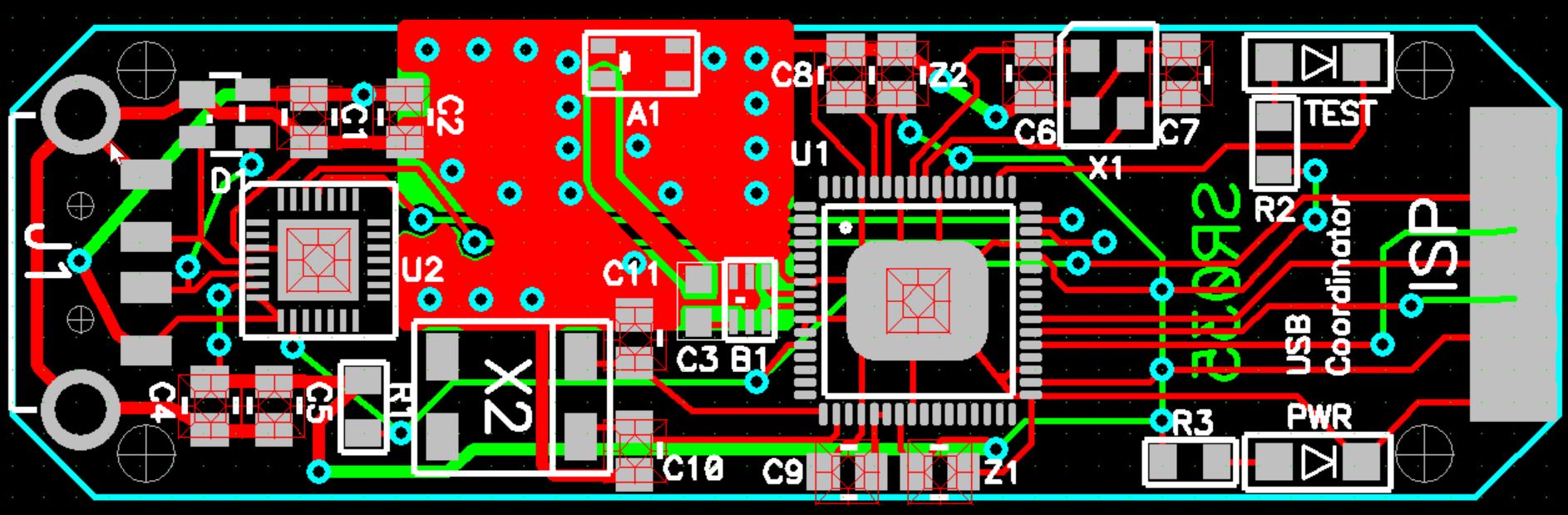
Solar collection – the SR2 panels were 36-watts and the SR3 panels are 44-watts. The energy collected by groups of six panels is brought together in what we call a Consolidator circuit board housed in either an electrical cabinet or a Cable Corridor. The Consolidator board routes power generated by the solar cells to the micro-inverter and provides power back to the LEDs and heating elements. At the Sandpoint installation, the micro-inverters feed the load center which runs the bathroom lights, a water fountain, the kiosk, overhead lights for the public square, etc. The solar installation is too small to run all of that on its own, but it offsets the amount of energy that the public square requires.
The Consolidator board arranges the solar energy collected by the six panels in a series/parallel configuration, including bypass and blocking diodes. This arrangement is done to meet the input requirements of the micro-inverters. By making adjustments to this circuit board, we’re tweaking the energy harvesting capabilities of the Solar Road Panels. We’re also experimenting with moving the solar cells within the panels for more optimal solar harvesting ability. To an engineer, it can always be made better. Years ago, I was designing a product line for a company in Ohio. Someone placed a sign above my door that read, “There comes a time when you just have to shoot the engineer and go into production!”.
The Jeff Jones Square installation in Sandpoint is a pilot project: a small-scale experiment to allow us to get “real world” empirical testing and make adjustments accordingly. When we first installed the panels, we adjusted the intensities of the LEDs under different sunlight conditions until we were able to create our first intensity table for the microprocessor to follow. When the snow was falling, we were experimenting with the best ways to operate the heating elements. Now that the sun is rising higher overhead, we’re tweaking the solar harvesting capabilities (although this seems to be the rainiest spring we’ve ever had, which makes our real world testing difficult!). We’ll post the energy link when we’ve finished tweaking everything for production.
While juggling hardware, firmware, and production, I’m also working on software which will allow the LED lights to be quickly and easily changed. Right now it’s still a cumbersome process, so we are not changing the lights very often. The software will soon change that and we’ll begin to show you all of the possibilities for LED lit surfaces.
We recently sent five of our Solar Road Panels to a university civil engineering lab for shear testing. Later this year, we’ll send out more panels for freeze/thaw cycling, moisture conditioning, and advanced loading (simulates 15 years of truck abuse in 3 months). This is all part of our third contract with the Federal Highway Administration. Stay tuned for the results.
I’ll blog about each subsystem in more detail as time permits. I hope this sheds some light on the technical side of things and on the complexity of our system. These aren’t your typical solar panels!